
INTRODUCTION
The treatment of displaced clavicle fractures has trended towards operative management since the landmark Canadian trial (Canadian OT 2007). Despite growing indications and prevalence for plate fixation, complications still occur during the execution of this routine but technically demanding procedure. Hardware failure rates of 4%, and probability of malunion (0.28), nonunion (0.29) and implant failure (0.39) have been reported (Navarro et al. 2016; Nourian et al. 2017).
Despite logarithmic technical advance over the last fifty years, the standard technique for fracture fixation remains largely unchanged. Drilling, based on the surgeon’s tactile feedback and depth gauges based on manual manipulation and limited precision introduce risk for error.
Drilling errors can be life threatening when vital structures are in close proximity, as in the medial clavicle, and anatomic studies confirm vital structures fall within the average plunge depth of conventional drilling techniques (Clitherow and Bain 2015; Chuaychoosakoon et al. 2019; Robinson et al. 2014). Inaccuracies of wire depth gauges and calibrated drill bit measurement can lead to screws of the wrong length, wasted screws, and increased reliance on fluoroscopy to insure optimal screw position and length. Screw exchange requires additional steps, increased surgical time, and may compromise pull out strength of the second screw.
Inaccuracies and inefficiencies with conventional drilling technology leaves opportunity to develop innovative drilling technologies that provide increased safety margins for patients and real time drilling data for optimizing surgical decision making. With this in mind, a dual motor orthopaedic drill (D-MOD) was developed to address the limitations of traditional techniques.
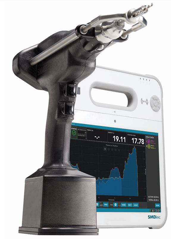
The D-MOD system ((SMARTDrill, Smart Medical Devices, Las Vegas, NV) contains a dual motor drill and a remotely linked tablet (Figure 1). The first drill motor spins a chuck similar to any drill but at a controlled revolution rate determined by the software (rpm). The second motor moves a harp and drill guide parallel to the axis of the drill bit controlling advancement of the bit. The second motor records the linear distance that the drill bit travels and provides continuous data back to the monitor.

During D-MOD drilling the drill guide is pressed against the bone holding the drill guide and harp static. Depression of the first trigger spins the chuck. Depression of a second trigger then allows the drill bit to move forward at a controlled rate sliding through the drill guide and into the bone. This allows the drill to function like a handheld drill press in which the harp and drill guide are a depth stop.
During drilling, the dual motor drill measures the work done by the drill bit by isolating the torque and rpm as it cuts. Data transmission to the tablet occures through an autoclavable wireless BluetoothTM communication system. A touch screen computer tablet displays real time drilling data and controls all aspects of drill function. A clear sterile covers allow the tablet to be placed in sterile field for ease of use.
Energy is plotted visually on a monitor with the drill bit depth on the x-axis and drilling energy on the y-axis. The drill works in a similar fashion for insertion of screws using a standard driving bit while demonstrating the instantanous torque and screw insertion energy.
In this example, we present the use of the D-MOD system to facilitate plate fixation of a comminuted mid-shaft clavicle fracture. The D-MODs ability to minimize plunge, accurately measure screw lengths, and gain insight into relative strengths of screw holes on either side of the fracture is described in detail.
CASE REPORT
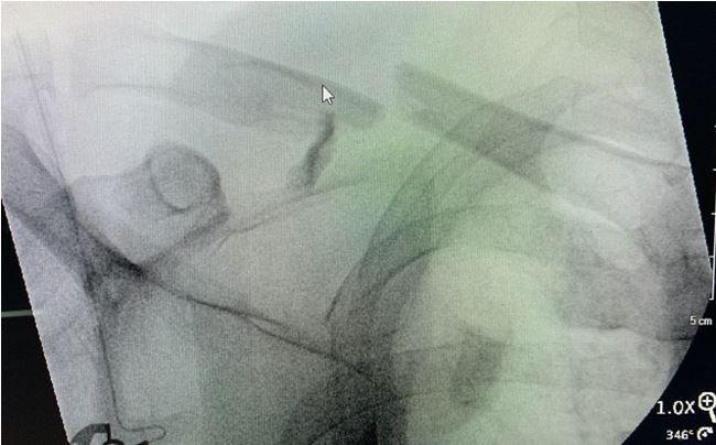
A 47 year-old male involved in a motorcycle accident sustained a comminuted mid-shaft clavicle fracture (Figure 2) and was planned for operative fixation. The surgeon and senior author, Dr. John Perry, co-founder of Smart Medical Devices, and developer of SMARTdrill, performed the procedure as described below.
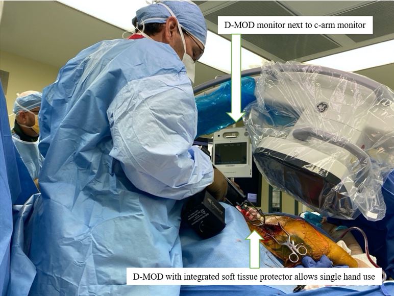
The patient was positioned on a radiolucent table in approximately 30 degrees of reverse Trendelenburg position with a bump under the scapula. The C-arm was positioned from the opposite side of the patient. The C-arm monitor and the D-MOD’s monitor were placed facing the surgeon near the patient’s contralateral hip. This positioning allowed full view of the clavicle exposure, fluoroscopic imaging, and drilling data (Figure 3). Exposure, reduction, and provisional fixation with a ten-hole curved small fragment plate was completed.

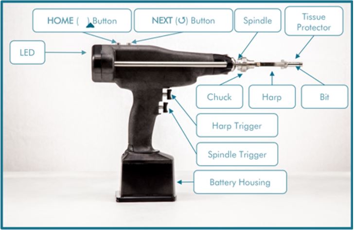
When preparing the D-MOD system, the proper tissue protector and drill bit are selected for the plating system being used. The drill is “zeroed” by matching the tip of the bit to the tip of the tissue protector using the lower ‘Spindle’ trigger and the upper ‘Harp’ triggers at the same time (Figure 4).

To start drilling, the surgeon depresses the Spindle trigger, which spins the bit, and then depresses the Harp trigger, which retracts the tissue protector, feeding the drill bit into the bone at the preset feed rate as the surgeon keeps downward pressure on the bone. In this case the bit was set to advance at a default setting of 1.5mm/second. In cases of higher bone density 1.0mm/sec may be used.
To ensure the drill is progressing forward through the bone and not just spinning on top of hard bone as the harp and drill sleeve retracts, an LED light ‘engagement sensor’ is incorporated on the back of the drill (Figure 4 “LED”). The engagement sensor flashes red when the drill sleeve is retracting away from plate or bone and alerts the surgeon that the bit is no longer advancing through the bone. Loss of engagement can be experienced when drilling hard bone with large diameter or poor performing bits. The surgeon may want to push down with more force or change to a sharper, clean, or new bit to ensure bone penetration. Engagement force measurements are displayed top center on the tablet screen. Once drilling is initiated and engagement is confirmed, the surgeon moves his attention to the digital monitor.
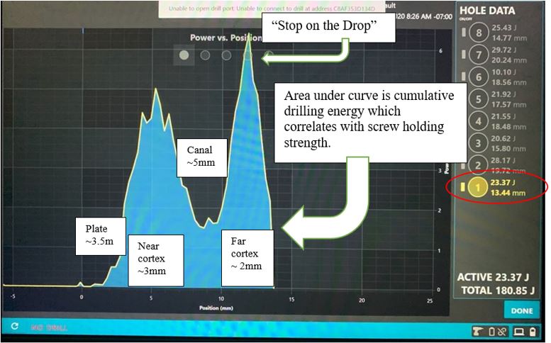
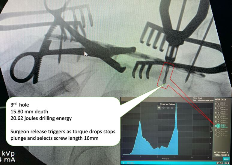
When the drill bit enters the bone the monitor will display a characteristic torque curve. (Figure 5) In bicortical drilling the torque will rise as the bit penetrates the first cortex, then fall, and then rise again as the drill bit enters the second cortex. To stop drilling, the surgeon releases both triggers to stop the bit and harp as the second curve drops (“Stop on the Drop”), which indicates the drill bit has penetrated the far cortex (Figure 6). After drilling the ‘Home’ button is depressed on the top of the D-MOD housing, and the tissue protector robotically travels back out to cover the drill bit to the original “Zero” point.


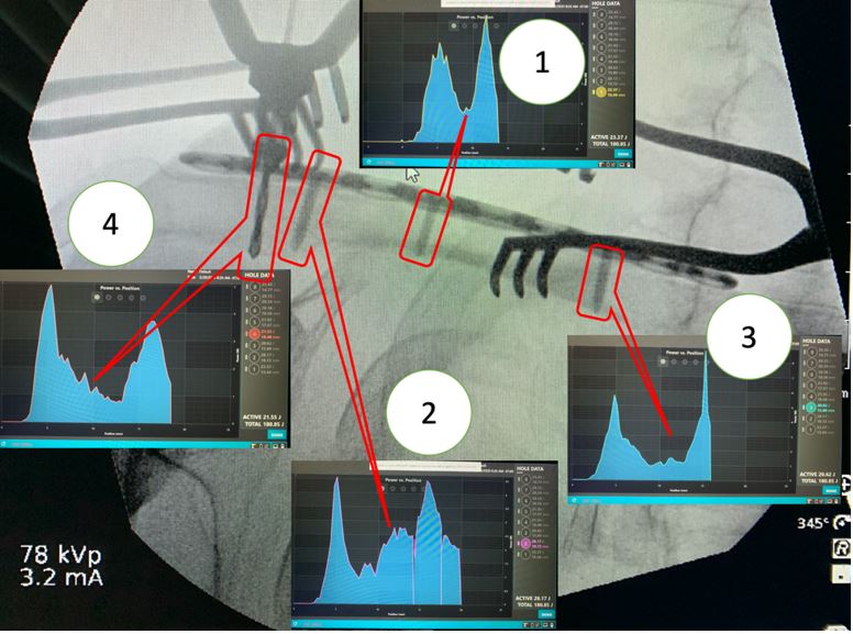
Drilling continues in this fashion for each of the necessary screw holes. As drilling continues, the drilling energy (represented by the area under the curve) is recorded for each hole. Drilling energy has been correlated to screw pullout strength, and therefore, the surgeon can decide if fixation will be adequate prior to placement of any screws (Gilmer and Lang 2018; Chen et al. 2020).
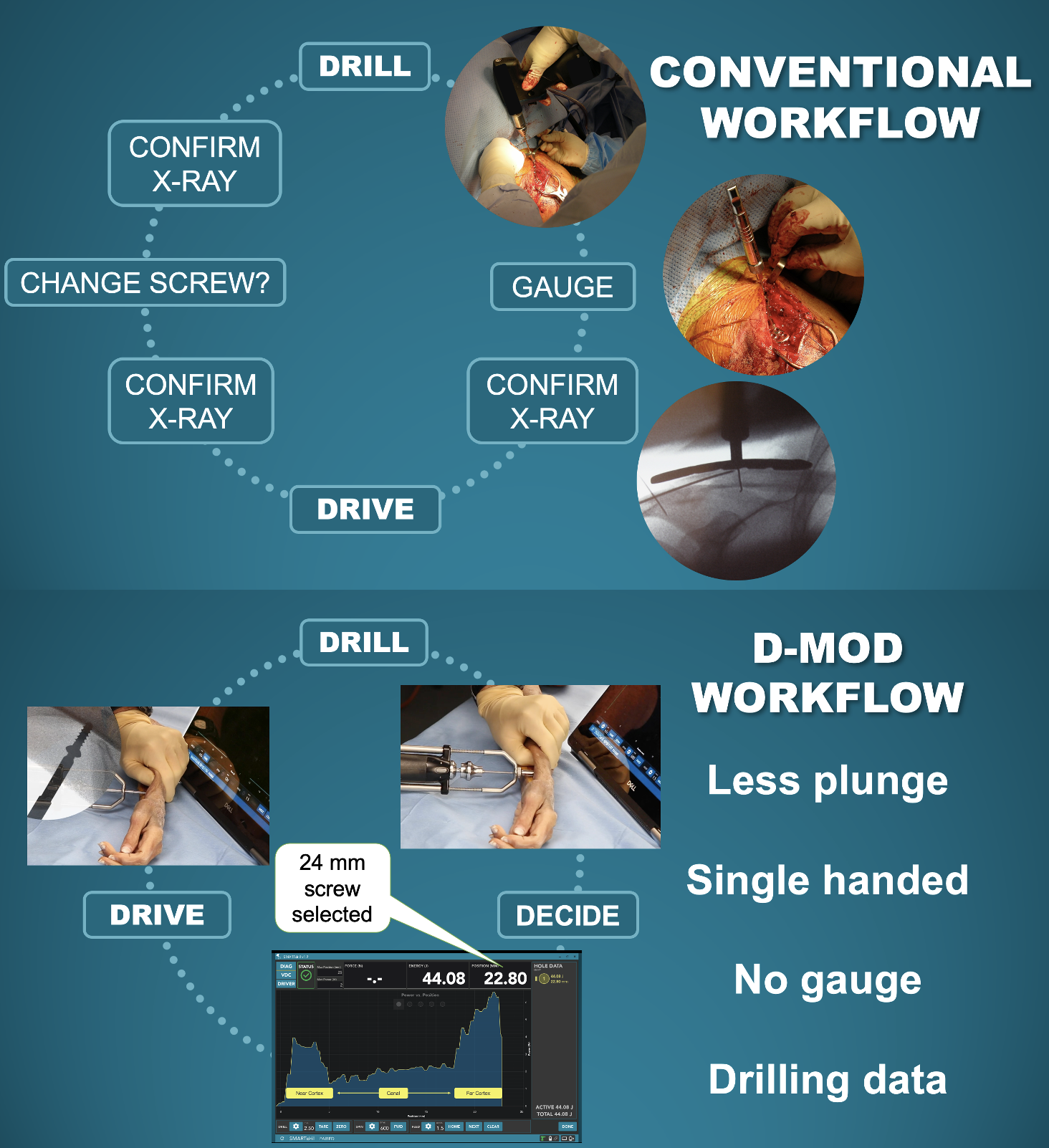
Once drilling is completed, the drill bit is exchanged for a standard driving bit and screw insertion is performed in a typical fashion. Alternatively, subsequent holes can be filled in sequence. i.e. drill, select screw, place screw, return drill guide to Home and repeat. (Figure 7). This process simplifies the work flow from the conventional model of drill, measure, fluoroscopy, screw insertion, fluoroscopy (and possible screw exchange) to “drill, decide, and drive.” (Figure 8)


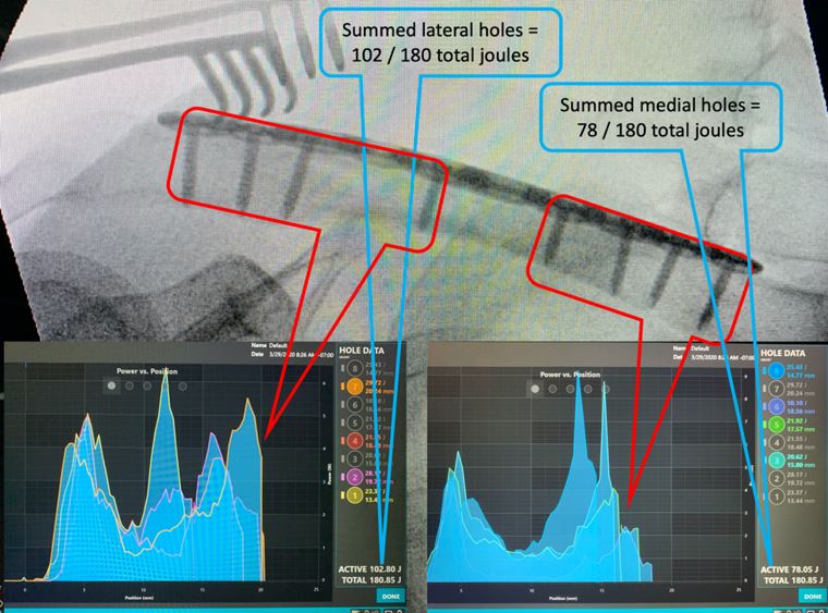
After fixation is completed, drilling energies and depths can be easily analyzed for fixation strength on each side of the fracture, or for the completed construct (Figure 9). The case is closed by pressing the ‘Done’ button on the lower right corner of the screen, and then saved if the surgeon desires for later documentation.

In this example, the fracture was plated without plunge events and without wasting a screw. Time may be saved due to the simplified work flow. Exposure to ionizing radiation may also be reduced as fewer confirmatory X-rays maybe needed to assess screw lengths.
DISCUSSION
Dual motor drilling eliminates many of the problems associated with traditional fracture fixation techniques.
The second motor and variable depth gauge controls unwanted overpenetration, or plunge, and at the same time allows for a stable reference point to measure the drilling depth. Combining the drill and guide in a single unit allows the surgeon to apply counterforce or irrigate with the hand that was previously used to hold the drill sleeve. The dual motor drill has proprietary autoclavable electronics and antennae that wirelessly transmit real time drilling data to the tablet. The drilling data includes continuous force, energy, watts, torque, time, and depth measurements that are displayed on the tablet’s touch screen. The surgeon can adjust drilling parameters like RPM and feed rate from the tablet while it displays instantaneous and continuous drilling data and performance as the bit cuts through the bone.
The D-MOD system has significant implications for clinical research as it provides objective data regarding fracture constructs. When feed rate and RPM are held constant, the value of of torque over time or distance can be converted to energy in joules. The cumulative energy required to create a pilot hole correlates with the energy needed for screw insertion into the same hole. This screw insertional energy can also be measured directly in D-MOD drive mode. Studies performed using the D-MOD system have confirmed that drilling energy and screw insertional energy correlate with pullout strength of screws (Gilmer and Lang 2018; Chen et al. 2020). The D-MOD demonstrates energy visually in the area-under-the-curve created during drilling or screw insertion and displays the total value for energy in joules on the digital display. (Figure 6)
The study of human bone is complicated by its heterogeneity between individuals and even within a given specimen. Bone is anisotropic and variable in physical properties of depth, density, porosity, strength, and lubricity. The D-MOD controls for several variables allowing accurate assessments of bone characteristics at any location where drilling occurs. A cadaveric tibia study found that D-MOD data on drilling energies better correlated with bone strength than did micro-CT or DEXA scan. Also, the D-MOD was more accurate than micro CT at measuring cortical thickness (Chen et al. 2020).
Clinically, the D-MOD system has the potential to improve safety, increase efficiency, reduce waste, and reduce exposure to ionizing radiation. Because the surgeon can ‘see’ the far cortex on the monitor and because the depth stop is constantly in contact with the bone overpenetration or plunge can be eliminated. Traditional technique relies on a surgeon’s ‘feel’ for penetrating the far cortex. This variable is related to experience and can never be completely eliminated because of the inherent delay in reaction time. The elimination of plunge with D-MOD system has been confirmed in laboratory and cadaveric studies and is independent of operator experience (Chen et al. 2020; Wallace et al. 2019; Lang and Gilmer 2020). Similarly, because the depth of the drill bit tip is known in real time, selecting a screw does not require a separate depth gauge or confirmatory fluoroscopy. Gilmer et al. demonstrated the D-MOD’s improvements in measurement accuracy and time saved in a surrogate bone model study (Lang and Gilmer 2020). More accurate measurement may lead to less need to exchange inaccurate screws and therefore cost savings may be realized. Finally, drilling data has been correlated with bone density, providing objective data to replace a surgeon’s subjective sense of poor bone quality that may require augmented fixation (Gilmer and Lang 2018; Chen et al. 2020).
In clavicle fractures specifically, anatomical studies have suggesting concepts of safe zones where implants can be placed safely (Thumroj, Kosuwon, and Kamanarong 2005). Other studies suggested that whether superior or anterior-inferior plate was selected there was no significant difference in proximity of neurovascular structures between the two screw trajectories (Hussey et al. 2013). Clitherow reviewed major neurovascular injuries after clavicle plating. These rare but life and limb threatening events included subclavian vein, brachial plexus and delayed subclavian artery injuries leading to pseudo-aneurysms (Clitherow and Bain 2015).
Some modifications are required when using the D-MOD system in clinical practice. When drilling directly on bone and the tip of the bit has been zeroed with the tip of the drill sleeve a surgeon must measure how much length to add to D-MODs true bone depth measurement to select optimal screw length. By convention manufacturers may include the head length in overall screw length measured by their wire depth gauge e.g. D-MOD bone depth measured 19.61mm and screw head is 4 mm then the surgeon may select a 24mm screw to ensure penetration of the far cortex. Plates can vary in thicknesses and wire depth gauges may typically be matched to the plates. When using the D-MOD through plates the true osseous depth can be seen on the screen. The surgeon then adds the amount of head engaged in the plate which maybe different between manufacturers and may need to be measured on the back table prior to drilling. This head length must be added to the osseous length to select the proper screw length. Once the surgeon has established the length added by a manufacturer, this process need not be repeated and can simply be added for subsequent screws.
CONCLUSIONS
Conventional single motor orthopaedic drills have been essentially unchanged for decades. Controlling the cutting drill bit tip is dependent on the surgeon’s senses and human reaction times. This technology fails to provide plunge prevention that can put vital structures at risk, provide no feedback on drilling performance or cutting efficiency to indicate bone strength, and require additional steps, time, and exposure to ionizing radiation.
The D-MOD system allows the surgeon to know where the drill bit tip is at all times without taking x-rays or stopping to look at calibrations on the drill bit or sleeve. The D-MOD system therefore allows for radiation-free continuous drill bit localization as the surgical team observes video monitor during the drilling and screw placement process.