
By sheer luck, my journey with kinematic alignment (KA) total knee arthroplasty (TKA) began in December 2005. At the time, I was performing 2 or 3 total knee replacements per week using mechanical alignment (MA), and I couldn’t figure out why some patients did well while others didn’t, even though the implants looked like a knee.
As Louis Pasteur opined, ‘Fortune favors a prepared mind.” Professor Maury Hull and I had already worked together for 17 years on the biomechanics of ACL reconstruction. From his cadaver testing machine, we knew that the knee had a single ‘kinematic’ axis in the femur about which the tibia flexed and extended, something very few knee arthroplasty surgeons and engineers knew at the time.
We also knew from Eckhoff’s 2005 article that MA changed the patient’s pre-arthritic joint surface in all but 2% of knees. They cleverly located the tibial flexion and extension axis by 3D-best-fitting a cylinder to the posterior femoral condyles on a bone model derived from a CT scan of the limb. The discussion reported a stunning observation that by altering the joint lines in nearly everyone’s knee, MA created a kinematic conflict between knee motion and ligament length.
This was our AHA! moment. We realized that the femoral head and ankle should not be used to align a TKA. We hypothesized that referencing the femoral head and ankle, and altering the joint lines, could explain some of the poor outcomes in our patients with MA TKA.
So, in mid-December, two engineers, Charlie Chi and Ben Park, with PhDs in robotics and manufacturing, asked to meet with us. They had an idea that grew into what became known as Patient-Specific Instrumentation (PSI).
Ben had a Plexiglas guide the size of a brick that mated to the distal end of the femur. He said it could be used to set the varus-valgus, proximal-distal, and flexion-extension positions of the distal femoral cut and the femoral component placement. I remember blurting out loud, “We could do the whole knee.”
These fellas amazed me with their ability to use open-source software. We chose a sagittal MRI of the patient’s knee to generate a 3D knee model to set the femoral component position and design a guide with a fit similar to a mouth guard for the distal femoral cut. Sagittal MRI was chosen over axial CT scans because it enabled better reconstruction of the distal and posterior joint lines and eliminated the femoral head and ankle from alignment decisions, which, even in 2026, remain utterly useless landmarks for performing KA.
Each week, we sent these ‘cut files’ to a 3D printing company, and they returned one set of guides to us in 5 days for use in the operating room. We used the first femoral guide in mid-January, and at 8 am the next morning, the lady was sitting up comfortably with the knee at 90 degrees of flexion, asking to go home—something unheard of at that time, at least for me.
Four weeks later, in mid-February 2006, we added the PSI guide for the tibial component. We called the concept, developed and field-tested in 6 weeks, ‘shape-match’, which aimed to resurface the knee to its pre-arthritic state. This definition of KA persists today and likely will remain so in perpetuity.
Our excitement grew when the presidents of the five major implant companies heard about what we were doing, and four visited us. They were impressed by the technology, but not much by me, as I was a sports surgeon with no fellowship training.
To stay competitive, they had to copy our concept. However, when they brought their engineers and thought leaders together, they made the egregious error of using MA. Unfortunately, the podium is still dominated by several of these thought leaders, who promote the same stale ideas.
So now you might ask, “How did shape-match morph into KA”? I coined the term to emphasize that the guides were designed to position the components to restore the three kinematic axes of the knees.
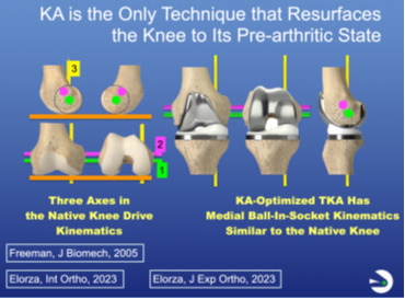
We are all indebted to Ann Hollister, a hand surgeon who described the F-E axis of the tibia in the femur in 1993. In 2003, Coughlin described the F-E axis of the patella in the femur, which is parallel to the first and to the distal and posterior femoral joint lines. In 2005, Freeman and Pinskerova showed that the internal-external (I-E) axis passes through the middle of the medial compartment, 4 mm posterior to the midline, and is nearly perpendicular to the tibial articular surface. Hence, only by resurfacing the knee to its pre-arthritic state can the axes and the patterns of ligament length change be restored during motion, mitigating joint surface binding and the need for ligament release, thereby enhancing recovery and function (Figure 1).
I loaned Charlie enough cash so OtisMed could rent space, purchase two four-axis milling machines, and build guides, which he repaid after securing $5 million in venture capital in September 2006. In three years, we sold 17,000 Otis Knee guides through the sales force for the Vanguard CR and Triathlon CR implants.
The stickiness of the OtisKnee was attributed to simplified surgery, rapid recovery, and a surprising increase in patient satisfaction. Surgeons observed that their patients did not require ligament release, which reduced perioperative pain and morbidity. An unexpected back-end benefit was fewer, shorter, and more pleasant postoperative visits, a windfall for those performing more than 300 TKAs per year.
Later in 2008, when the FDA requirements for PSI changed, we entered the approval process by claiming that the Hungerford-Krakow concept of anatomic alignment served as a predicate for KA. In September 2009, the approval was denied because we planned the tibial cut based on the distal femur rather than independently, a step that remains a critical and simple KA balancing step in 2026 when using manual instruments.
So I pivoted and developed manual instruments, which we now know perform KA femoral resections more accurately than robotic systems. I introduced the concept in November 2009, when I wrote my Insall & Scott book chapter on KA and uploaded a KA surgical technique video to www.VuMedi.com, which gave me a worldwide audience.
I used these two educational portals to make KA open source, without copyright or patent protection, because it helped surgeons help patients. I am indebted to the international surgeons who published studies validating the KA concept. In 2018, with a bit of help from me, those studies led to FDA approval of KA for two implants designed for mechanical alignment (Medacta GMK Sphere and Persona CR).
What really surprised me was that KA didn’t catch on more quickly. Two analyses offered a reason. One is that the average difference in the Forgotten Joint Score (FJS) between KA and MA, reported in six randomized or case-matched studies, favored KA by 12 points. A notable improvement, but not rocking the foundation of alignment theory, as it sits right at the minimal clinically important difference of 14.
What we did not report, because it was not typically measured, was the rapid recovery provided by KA. For me, patient recovery became more consistent and discernible, especially when I switched from the hemophilic effect associated with Coumadin, which was difficult to regulate, to aspirin for pulmonary embolism prophylaxis. By lowering the risk of thigh bleeding and muscle pain, recovery became more consistent.
Another reason KA was slow to catch on was that we were using MA-designed implants. Later, we stumbled across the error. Let me explain how this understanding came to light.
At the end of 2016, after 10 years of experience, the Professor and I examined clinical outcomes among my first 900 KA TKAs with Vanguard CR, followed by 1,300 Triathlon CR, 500 Sigma CR, and >2,300 Persona CR. None of the implants moved the needle! Why?
We hypothesized that they’re all the same design, with low-conforming medial and lateral compartments and a posterolateral rim on the insert. The posterolateral rim proved to be an unanticipated design flaw, with a devastating kinematic effect: blocking native internal tibial rotation during flexion.
Blocking internal tibial rotation during flexion causes the component’s medial femoral condyle to paradoxically translate anteriorly at 90 degrees of flexion, over-tensing the medial soft tissues, causing pain and slowing the return of motion and functional recovery. Our subsequent fluoroscopy publications compared the low-conforming MA design with a KA-optimized implant featuring a lateral flat insert articulation and a medial ball-in-socket design and reported this abnormal kinematics.
By 2017, I thought KA would never catch on. All the companies that made the implants I used had promised me, one by one, “We’ll develop KA for you.” I believed them for a while until I realized they were putting me on the back burner to keep me off the playing field.
And then I attended the AAOS in 2017 in San Diego. Now, remember, I am homeless, with no hope of launching KA, and my rep says, “You ought to go by and see these engineers at the Medacta booth.” I said to him, “Who are they?”
What I found was that they had launched a PSI version of KA under the expert guidance of Professor Venditolli in Montreal. Based on his experience and others’, they saw clinical improvements with his ‘restricted version of KA’.
Francesco Siccardi, then a VP of Medacta and now the CEO, had a rare openness to evaluating KA without inclusion or correction limitations. I think it helped that I had 11 years of experience with this ‘unrestricted’ KA version in > 6000 consecutive TKAs. We had already reported that varus implant failure with KA TKA was much rarer than in MA TKA. In 2026, I believe we can both say we are grateful for deciding to work together.
In August 2017, Medacta sent me the best KA manual instruments I had ever used. I began performing KA with the GMK Sphere, designed by Freeman and Pinzkerova.
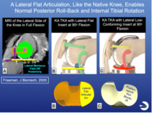
The first time I looked at the lateral compartment through the medial mid-vastus arthrotomy, with the patella reduced and the knee in 90 degrees of flexion, I was stunned. The posterior rollback of the lateral femoral condyle was near the posterior edge of the insert, something we had never seen with any of the other MA-designed components (Figure 2).
_on_the_lateral_side_of_the_native_knee_in_deep_flexion__the_hypermobile_lateral_menisc.png)
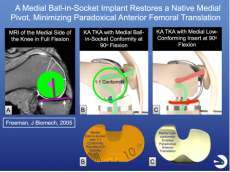
I quickly ruled out malalignment of the tibial component by double-checking that I had correctly ‘best-fit’ the anatomic baseplate to the tibial resection. My sales consultant, Larry Walsh, and I gradually realized that the lateral flat insert’s articulation allowed the component’s lateral femoral condyle to roll back posteriorly normally. In contrast, the posterolateral insert rim of all MA-designed implants blocked this motion. We also understood the reason Freeman and Pinckerova chose a medial 1:1 ball-in-socket conformity, a crucial ingredient for restoring the native knee’s medial pivot and a KA-optimized design (Figure 3).
_on_the_medial_side_of_the_native_knee_in_flexion_up_to_120___the_center_of_the_medial_.png)
I am indebted to the level-one, randomized controlled trials (RCTs) of KA TKA by French and Scott. In French’s 2020 RCT, the FJS score with a KA-optimized design was 16 points higher than the Vanguard CR at one-year follow-up (French et al. 2020). Similarly, Scott reported in 2022 that the KA-optimized implant group had a 10-point higher FJS score and 8 degrees greater flexion than the PS implant group at 2-year follow-up (Scott and Gray 2022). We quickly learned that switching from the MA-designed implant provided an FJS boost similar to switching from MA to KA, suggesting a synergistic effect from the combination.
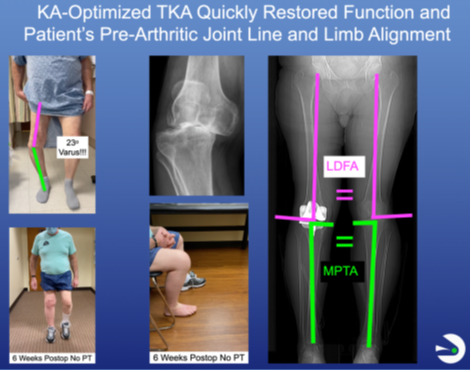
Two things happened from 2018 to 2026. The first was the shift to outpatient same-day discharge, facilitated by KA-optimized TKA. Andrew Wickline showed that his perioperative protocol, which eliminated physical therapist (PT) treatment in 85% of patients, dramatically lowered opioid use. Our work confirmed his findings and showed that 80-90 patients regain function as quickly as 50-60-year-olds, all by eliminating the physical therapist’s aggravation of the inherent tsunami of knee swelling that peaks at 6 days and lasts for 6 weeks (Akhtar et al. 2024) (Figure 4).

The second was to address potential patellofemoral concerns, especially in valgus knee deformities, that we attributed to having no choice but to use MA-designed femoral components featuring a 6-degree valgus prosthetic trochlear groove (PTG) with KA. Professor Hull and I provided some insight into changing the PTG and optimizing the femoral component for KA.
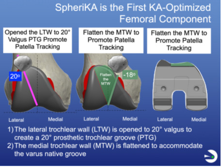
In 2020, Medacta conducted 3D modeling studies suggesting opening the lateral wall of the prosthetic trochlea to 20° of valgus and flattening the medial wall (Figure 5). In 2023, Rosa confirmed these trochlear modifications by noting that the native trochlear groove ranges from 20-degree valgus to 18-degree varus after discarding 1% as outliers.

The so-called SpheriKA, first implanted by me in November 2021, completed the KA-optimized implant design. The modification effectively addressed patellofemoral issues by increasing the mean FJS to 75, exceeding the success threshold of 70 reported for anterior hip arthroplasty, and increasing the FJS by 7, 20, and 43 points in CPAK II, III, and VI, with no detrimental effect in CPAK I.
In 2026, my overarching concern is that the principles on which KA is based are being hijacked. Other companies are competing and putting their spin on it. But it’s a straightforward concept, as I mentioned: resurface the knee to the pre-arthritic state.
I decided to use video courses to tell KA’s story for interested orthopedic surgeons. I developed a website called the KA-optimized TKA Education collective (www.kaoptimizedtka.com), which launched on Jan 15, 2026.
The first course, Core Curriculum, takes 2 ½ hours to complete and includes 18 video lessons averaging less than 8 minutes each, plus 18 quizzes with 4 multiple-choice questions each. Passing them earns a Record of Completion and access to the Educational Collection. The second course, Challenging Cases, is 90 minutes long and includes 11 lessons. Each point made by Professor Hull, Alexander Nedopil, and me is backed by a peer-reviewed article listed in a shareable list of abstracts. Many of these publications are available as downloadable PDFs.
We encourage those with different views to join, contribute new courses, take part in chat room discussions, and help shape and advance the future of KA-Optimized TKA, the gold standard procedure in 2026
Stephen Howell, MD, is a retired non-fellowship trained orthopedic surgeon and Adjunct Professor of Biomedical Engineering at the University of California Davis.
Maury L. Hull, PhD, is a Distinguished Professor of Mechanical and Biomedical Engineering, which he founded and chaired at the University of California Davis.