


Introduction
Tendons and ligaments are involved in 16.5 million musculoskeletal injuries each year in the United States (Wu, Nerlich, and Docheva 2017). Since tendon and ligament tissues have restricted regeneration capabilities due to limited vascularity, surgical repair or reconstruction is often required for rupture and tear injuries (Yang, Rothrauff, and Tuan 2013). In fact, in the United States, there are approximately 300,000 anterior cruciate ligament (ACL) reconstruction surgeries performed annually (Chang et al. 2011). During surgery, suture tensioning and subsequent relaxation play a critical role in repair and reconstruction success rates as over-tightening restricts joint movement and leads to graft breakdown while under-tightening causes joint laxity (Jin et al. 2022; Morrison et al. 2018; Sherman et al. 2012; Pereira et al. 2021). While many intra-operative technologies for measuring suture force tension before graft fixation have been developed to aid with placement of the femoral anchor and graft tightening, none allow the surgeon to measure suture loading after final graft fixation (Sherman et al. 2012; Piskopakis et al. 2023). Current methods for estimating graft placement, tensioning, and subsequent relaxation rely on cadaver models and computer simulations (Kaseta et al. 2008; DeFrate 2017). Cadaver model testing requires complex and costly equipment and can only provide generalized, non-patient specific information about surgical methods. Computer models can utilize patient-specific anatomy but are limited by material and boundary condition assumptions and cannot fully capture in vivo graft loading behavior. After surgery, early mobilization and physical therapy are vital to restoring tendon and ligament tissue function (Aufwerber et al. 2020). However, rehabilitation guidelines are highly variable and lack personalization as a result of differences in patient anatomy, healing rates, and pain tolerance, making it difficult to optimize standard physical therapy programs for safe and effective recovery (Senese et al. 2018; Filbay and Grindem 2019; Buckthorpe 2019).
A tool that could provide real-time suture loading biofeedback after final graft fixation would assist both surgeons performing graft tensioning and physical therapists during post-operative rehabilitation care. For example, ACL graft stress and strain have been shown to be affected by surgical parameters such as graft tension (Heis and Paulos 2002), graft stiffness (Marieswaran et al. 2018), and tunnel angle (Cheng et al. 2021) as well as knee angle (Marieswaran et al. 2018) and movement type (Escamilla et al. 2012). Thus, measuring suture loading and graft security after final fixation as the surgeon completes graft function and range of motion testing could provide insight on many unanswered clinical questions including how tight grafts should be tensioned during surgical reconstruction and if graft tension is maintained after the patient leaves the operating room. Determining the extent of graft loosening could further clinician understanding of differences in clinical outcomes through surgical planning with varying graft choice, graft tensioning protocols, suture material selection, and reconstruction techniques (Marieswaran et al. 2018). Information on suture tension post-fixation could also allow the surgeon to double check that the graft is properly anchored with correct tension during the operation in order to reduce graft failure rates and prevent revision surgeries.
In addition to assisting with intra-operative graft tensioning techniques, suture loading biofeedback could aid in determining ideal rehabilitation intensity, duration, frequency, and exercise types to personalize post-operative physical therapy (Filbay and Grindem 2019). Studies showed that graft forces range from 40 N to 300 N during gait (Marieswaran et al. 2018) and the peak native ACL forces range from 0 N (non-weight bearing seated knee flexion) to 1294 N (weight bearing single leg landing exercise) (Escamilla et al. 2012). Thus, quantitatively studying the biomechanical forces exerted on tendon and ligament sutures in vivo during physical therapy could help identify recovery milestones to further facilitate evidence-based rehabilitation care as well as provide early detection of graft or fixation failure.
One strategy to engineering clinically practical implantable sensors that provide suture loading biofeedback includes sensitizing existing suture accessories (e.g., suture anchor, button, pledget, and clips) (Karipott et al. 2022; Meyers and Ong 2022). Advantages of incorporating sensors into suture attachment devices, rather than sensitizing sutures themselves, consist of preserving suture manufacturing processes and suture material selection preferences by healthcare professionals, increasing the likelihood of clinical adoption. Sensitizing suture accessories already used in clinics also preserves surgical operation workflow and prevents any further alterations in the wound healing environment (i.e., scarring, fistula formation, contact damage, etc.) by the physical presence of implanted sensor devices that are not typically used in tendon and ligament repair surgeries. Additionally, since most suture accessories are chronically implanted, potentially harmful secondary surgeries where further scarring and infection can occur, are not required for sensor removal. Specifically, this paper presents a loading sensor, in the form of a suture button accessory, that is battery-free, wireless, and compatible with existing FDA-cleared implantable suture buttons. In orthopedics, a suture button is a suture fixation device designed to secure ruptured tendons, ligaments, and grafts to bone. Common examples of procedures that apply suture buttons include ACL, posterior cruciate ligament, ankle syndesmosis, biceps tendon, glenohumeral joint stabilization, and acromioclavicular joint stabilization surgeries (Altmeppen et al. 2022; Synovec et al. 2019; Cook et al. 2017; Fox et al. 2008; Shao et al. 2020; Wang et al. 2020; Tang and Zhao 2021).
Methods
To maximize the potential clinical impact of an implanted suture loading biosensor, the suture button accessory sensors are battery-free and operate wirelessly. The sensor is comprised of a resistive strain gauge, incorporated into an inductive-capacitive-resistive (LCR) resonance circuit where changes in suture loading alters strain gauge resistance. Varying the resistance of the circuit modifies the resonance behavior of the sensor, which can be remotely monitored with an external detection device via electromagnetic coupling to determine suture loading force. The sensor was designed as a suture button supplement or accessory which enables compatibility with existing orthopedic surgical procedures and does not require revisions to commercially available suture button devices. Finite element analysis (FEA) was first utilized to evaluate and optimize suture button accessory deformation and strain for the sensors’ resistive strain gauge components under various loading conditions. After sensor fabrication, the sensitivity, loading ranges, and repeatability of the sensor was characterized with mechanical testing. Transmission capabilities between the implantable sensor and the external detection device were also tested by varying alignment and orientation. Finally, incorporation of the sensor in a cadaver knee with a reconstructed ACL was performed to demonstrate sensor detectability and functionality in tendon/ligament repair. Overall, the suture button accessory loading sensor technology developed in this work could aid healthcare professionals with intra-operative graft tensioning and in the personalization of post-operative rehabilitation exercises to increase the safety and efficacy of physical therapy practices.
Sensor Design and Fabrication
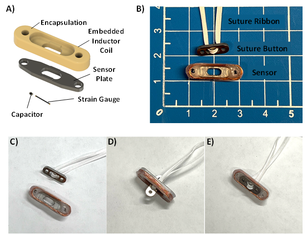
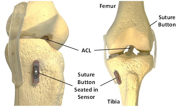
The suture button sensor accessory consisted of a machined titanium alloy (ASTM F136; McMaster Carr; Elmhurst, IL) sensor plate, 30 pF surface mount multilayer ceramic capacitor (Samsung EM, Korea), resistive semiconductor strain gauge (Micron Instrument; Simi Valley, CA), and an 8-turn inductor coil composed of 32 AWG copper wire (Remington Industries, Jonhsburg, IL) (Figure 1A) in the shape of an oval race track. Adhesive (M-Bond 610; Micro-Measurements, Wendell, NC) was applied following manufacturers recommendations to secure the strain gauge onto the sensor plate substrate. The suture button accessory sensor is designed to hold conventional suture buttons 18 mm × 4 mm × 1.2 mm or smaller in size. The sensor was encapsulated with high-density polyethylene (Sigma Aldrich, St. Louis MO) by compression molding at 210 °C in a convection oven (10GC Analog Lab Oven, Quincy Labs, Burr Ridge, IL) for 45-60 minutes using a custom aluminum mold. The assembled suture button accessory sensor size was approximately 22 mm × 7 mm × 4 mm (Figure 1B). The suture button sensor accessory was developed to work with commercially available suture buttons with similar claims as Smith & Nephew’s® XTENDOBUTTON™, a suture button extension designed to prevent cortical blowout, inhibit button pull through, and center the button at the bone tunnel interface (Jie and Wang 2021; Struhl and Wolfson 2015). Arthroscopic deployment of a suture button into the sensor consists of passing the suture button through the rounded rectangular through-hole in the sensor plate and then rotating the suture button into position to seat on the sensor (Figure 1C-E). Many variations of surgical fixation methods that incorporate suture buttons for ACL reconstruction exist. One example of the suture button sensor deployed in an ACL reconstruction includes placing a suture button over the bone tunnel on the lateral epicondyle of the femur and tensioning the graft with the suture button sensor at the medial tibial anchoring point (Figure 2).
._an_assembled.png)
_reconstruction_kne.png)
Sensing Mechanism
The suture button accessory sensor forms a resonance LCR circuit with the inductor coil (Ls), capacitor (C), wire resistance (Rw), and resistance from the strain gauge (Rs) (Figure 3). Remote transfer of power and data is achieved through electromagnetic coupling between the sensor and an external detection device coil (Ld) (Figure 3). Suture loading force is transduced through alterations in resonance behavior, specifically quality factor (Q). Quality factor (Q factor), a dimensionless parameter that quantifies the sharpness of a resonance spectra, is the ratio between resonance frequency (f0) and half power bandwidth (B) (i.e., the bandwidth between the two frequencies with signal strength equal to 70.7 % of the resonance amplitude) and defined as follows (Karipott, Veetil, et al. 2018):
Q=f0B
Q factor is also influenced by inductance (Ls), capacitance (C), strain gauge (Rs) resistance and wire resistance (Rw) as follows (Karipott, Veetil, et al. 2018):
Q=1Rw+Rs√LsC
Since the Ls, C, and Rw components are held constant in the sensor, Rs, the strain gauge resistance, becomes inversely proportional to Q as long as Rw << Rs according to (2). An example of a measured impedance spectra from the suture button accessory loading sensor and Q factor calculation method are highlighted below (Figure 4). Suture loading force is transduced through deformation of the sensor plate containing the adhered strain gauge. As suture tensile force compresses the suture button against the suture button accessory loading sensor, strain is applied to the sensor plate which increases the resistance of the attached strain gage, decreasing the remotely measured quality factor of the circuit as outlined in (2).


Detection System
For all benchtop data recordings, the suture button accessory sensor was monitored using a network analyzer (E5061B ENA Vector Network Analyzer; Keysight, Santa Rosa, CA) with a power output of 10 mW through a coil antenna. The coil antenna was composed of two-turn 18 AWG magnet wire wrapped around a 3D printed form. Coil antenna size was approximately 20 mm in diameter. Resonance data acquired through the network analyzer was collected with a custom Visual Studio program (Microsoft Corporation, Redmond, WA) to calculate the Q factor. Each sensor resonance was recorded as an S11 parameter via the network analyzer with an averaging number of 10 and each frequency sweep contained 200 discrete frequency points around the sensor resonance frequency. During the cadaver testing, a handheld network analyzer (nanoVNA-H, Shenzhen Zhuoyu Technology Co., Shenzhen, China) with a power output of 0.1 mW was used due to its portability.
Suture Button Accessory Sensor Loading
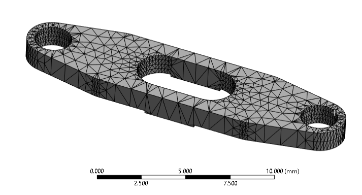
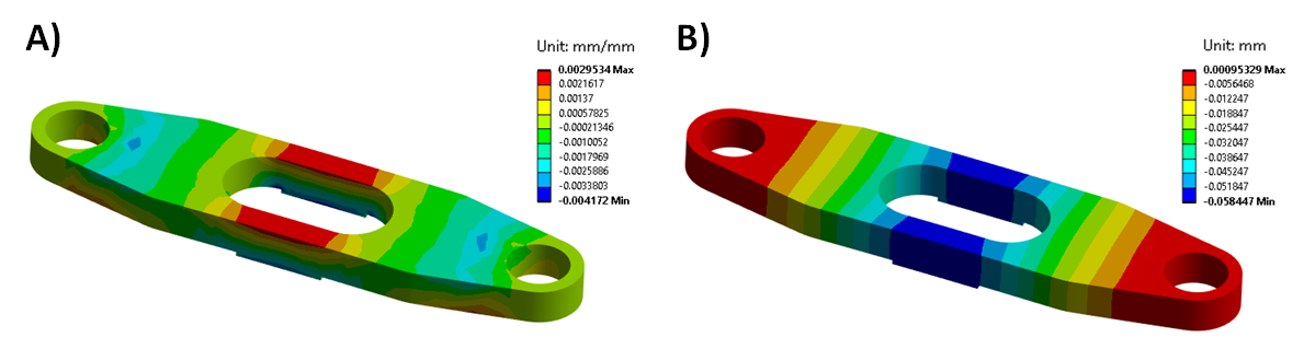
Strains and deformation experienced by the suture button accessory sensor were first visualized with static structural simulations in FEA software (Ansys Workbench; Ansys, Canonsburg, PA, USA). The titanium material used to model the sensor plate was assumed to be linearly elastic over the applied loading range with Young’s modulus of 113.8 GPa and a Poisson’s ratio of 0.342. Tetrahedral elements ranging from 0.1 to 0.5 mm in size were used in the sensor plate mesh (Figure 5). For all simulations, the bottom feet of the sensor plate (the areas that contact bone) were fixed while a ramped 180 N force was applied to the areas of the sensor plate that contact the suture button.

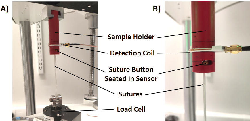
For mechanical testing, the tensile loads experienced by an implanted suture button were mimicked by applying tension on a Force Fiber© suture (2 mm UHMWPE, Teleflex, Wayne, PA, USA) looped through the holes of a suture button that was seated in the suture button accessory sensor. For all loading studies, a mechanical testing system (ElectroForce 3200; TA Instruments, New Castle, DE) was utilized with a machined sample holder composed of Garolite (G10-FR4; manufacturer) (Figure 6). To characterize sensitivity, ramped loads varying from 5 to 180 N with 10 N intervals were applied to the suture button accessory sensor. Measurement hysteresis was evaluated by comparing sensor response during both loading and unloading conditions. Drift was then assessed with repeated loading from 5 N to 100 N over 5 cycles at a rate of 4.5 N per second. Repetitive loading from 5 N to 180 N over 10,000 cycles at a rate of 1 cycle per second was also performed to assess any alterations in sensitivity. A tension cycling was done between 5 N to 20 N at the rate of 5 N per second for 10 cycles before each test to minimize stress relaxation in the suture. For all mechanical testing experiments, suture button accessory sensor Q factor was measured as a function of suture loading and each data point was collected and averaged simultaneously with applied loading.

Detection Alignment and Orientation
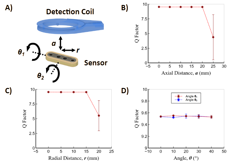
To characterize the effects of alignment on signal transmission between the external detection coil and implanted sensor, the sensor response (Q factor) was measured as a function of its relative orientation and position from the detection coil. Specifically, the sensor was tested under various axial displacements, radial displacements and relative angle changes between the sensor and the detection coil.
Sensor Deployment in Reconstructed Cadaver Knee
A cadaver knee joint (male, age 92, extremity side left) from mid-femur to mid-tibia with intact skin and subcutaneous tissues was obtained to simulate an ACL reconstruction surgery with the suture button accessory sensor. A sports medicine fellowship trained orthopedic surgeon performed the ACL reconstruction. To generate an ACL graft, the semitendinosus was harvested using an open tendon stripper. The tendon was then quadrupled over an Arthrex Tight Rope® RT on the femoral side and an Arthrex® Attachable Button System (ABS) loop on the tibial side, creating a 10 mm × 70 mm graft. A medial parapatellar arthrotomy was performed and the patella retracted laterally. The native ACL was removed by sharp dissection. A 10 mm × 25 mm femoral tunnel was then prepared using an outside-in guide and a FlipCutter III® retrograde reamer. The tibial tunnel was reamed over a 2.4 mm guide pin using a 10 mm barrel reamer. In standard fashion, the graft was shuttled into place and the TightRope® RT deployed under direct visualization on the lateral femoral cortex. The TightRope® RT was then shortened to allow 20 mm of graft in the femoral socket, 30 mm in the joint, and 20 mm in the tibial tunnel. Sensor deployment was achieved by placing the accessory sensor over the top of an Arthrex 12 mm button on the tibial ABS suture loop (Figure 7). Graft tensioning was performed using the standard clinical practice of applying maximal manual tension with the knee in full extension. The skin was closed in layers with monofilament suture. After superficial tissue suturing, the detection coil was placed over the site with the sensor and held in place with the help of plastic wrap. A handheld network analyzer connected to the detection coil was used to measure sensor output during Lachman testing and cyclic flexion of the reconstructed knee joint. Cyclic flexion was performed manually from full extension to 120° of flexion.

Results
Suture Button Load Detection
Simulated loading of the suture button accessory sensor plate was performed to visualize areas of high strain and deformation to determine ideal placement and geometry of the strain gauge in the sensor design. Strain in longitudinal direction of the suture button accessory sensor plate at 180 N of simulated load reached approximately 0.003 mm/mm in the area where the strain gauge was adhered to the sensor plate (Figure 8A). The deformation magnitude of the sensor plate was greatest (0.06 mm) in the direction of applied loading that also corresponded with the area where the strain gauge was adhered to the sensor plate (Figure 8B). Since the sensing mechanism of the sensor is based on suture button accessory deformation, loading ranges can be tuned by simply altering the geometry of sensor plate. For example, increasing the thickness or width of the sensor plate beams adjacent to the adhered strain gauge increases the loading magnitude required to achieve the same deformation and strain, allowing the sensor to function at a higher loading range. Actual or measured strain and deformation are expected to be lower than simulated results since sensor encapsulation materials were not included in the simulation.
_and_deformation.png)
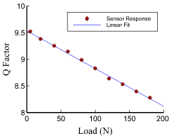
The resonance frequency that the sensor functions at was approximately 24 MHz which falls within the high frequency portion of radiofrequency spectra (3-30 MHz). This frequency range was selected because electromagnetic radiofrequency attenuation is greater in higher frequency ranges and reduces detection range limit. Mechanical testing of the suture button accessory sensor indicated that suture loading and unloading between 5 N to 180 N was indirectly related to changes in the sensor’s Q factor (Figure 9). The sensitivity of the suture button accessory sensor was -7.08×10⁻³ N-1 and the full-scale output (FSO) was 1.24 (Q factor) for the tested loading range. Any differences in sensor output between the loading and unloading directions was not measurable indicating little to no hysteresis. Loading magnitudes that tendons and ligaments experience are largely dependent on their locations in the body. The tested loading range of the suture button accessory sensor is applicable to the estimated tensile forces an ACL undergoes during some non-weight and weight bearing exercises that are performed during rehabilitation (Escamilla et al. 2012; Dargel et al. 2007). However, during more intense exercises and movements, the ACL may experience tensile loads approaching 500 N, but these types of exercises and movements would be performed during later stages of physical therapy when the healing ligament tissue bears the majority of the load rather than the sutures anchored to the suture button accessory sensor (Marieswaran et al. 2018). By altering the geometry or material composition of the sensor plate, the sensor loading range can be adjusted to accommodate for greater load magnitudes. Furthermore, using different strain gauges provides another means for modifying sensitivity and loading ranges.
Since tendon and ligament tissues experience recurring motion, especially during physical therapy exercises, the ability of the suture button accessory sensor to reliably perform under repetitive loading is critical. Cyclic mechanical testing indicated that repetitive loading of the suture button accessory sensor from 5N to 100N did not produce any measurable drift or change in sensitivity over 10 cycles of recurring loads demonstrating the repeatability of platform (Figure 10A). After loading the suture button accessory sensor from 5 N to 180 N for 10,000 cycles, a 1.8 % change in sensitivity was observed (Figure 10B). The relatively low sensitivity change suggests that the sensor is able to withstand fatigue cycles and the low change can be attributed to the strain sensor operating well within its operating strain range. Device failure was not tested in the study as the device functionality was only evaluated up to 180 N. Operating loads on the device in ACL reconstruction are not expected to be above this range during intra-operative deployment and post-operative rehabilitation. Future studies will determine device failure loads and modes while device design will be altered to adjust loading operation ranges if needed.

._sensitivity_.png)
Sensor Transmission Characterization
Understanding alignment requirements between implanted sensor and external detection coil during sensor recording sessions is vital to the function of the technology. Coupling limitations were characterized by varying the displacement and orientation angles between the sensor and detection coil (Figure 11A). The sensor demonstrated a reliable performance in a detectible range of 20 mm along the axial direction, and 15 mm along the radial direction of the detection coil (Figure 11B-C). Furthermore, measured Q factor variation remained within 0.1 when the sensor was angularly misaligned up to 40 degrees with respect to the detection coil (Figure 11D). Detection range is significantly influenced by the operating power of network analyzers. Increasing the operating power would improve detection range and decrease signal to noise ratio. Since suture buttons are available in a variety of different shapes and sizes and the form factor of the suture button accessory sensor also influences coupling, the geometry and size of the sensor can be altered as needed to improve detection range. Initial alignment and transmission distance experiments were performed through air. Future studies will fully characterize signal transmission through skin and subcutaneous tissues.
__axial_(*.png)
Sensor Function in Reconstructed Cadaver Knee
A cadaver knee ACL reconstruction with the suture button accessory sensor at the tibial anchoring point was utilized to evaluate sensor deployment and detection. First a Lachman test was performed as the ACL resists anterior tibial translation and internal tibial rotation to aid in rotational stability 33]. Results indicated that the suture button accessory sensor could wirelessly quantify loading experienced by the sutures and graft with manual anterior tibial translation (Figure 12A). Cyclic flexion of the knee joint also showed that the sensor recordings could capture graft relaxation during repetitive loading (Figure 12B). Specifically, graft suture loading was greatest during full extension of the reconstructed knee joint and lowest at 120° of flexion. As cyclic flexion was applied to the reconstructed knee peak loading during full extension decreased from approximately 90 to 70 N after 5 cycles of loading demonstrating relaxation in the ACL suture-graft construct. This suture button accessory sensor is the only known technology that can wirelessly and directly measure suture force loading after final button fixation. Both of the knee manipulation tests show that the suture button accessory sensor can successfully quantify force loading intra-operatively and post-operatively following the patient joint reconstruction.
_and_cyclic_flexion_of_the_.png)
Discussion
While the suture button accessary sensor can measure the tensile force, there is still a lack of research data to correlate these measurements to clinical outcomes that can assist medical decision-making process. Therefore, prior to full clinical implementation, this sensor system will need to be used in conjunction with a wearable detector that measures limb position and motion and the extent of limb mobility over the period of rehabilitation. These motion and position measurements, along with the physician’s evaluation, will provide data necessary to establish relationships between the sensor measurements (i.e., tendon/ligament tensile load) with previously established clinical outcome (e.g., range of motion).
Although sensor functionality and compatibility were verified with an ex vivo ACL cadaver reconstruction model, improvements are still needed for clinical deployment of the sensor, especially for post-operative monitoring. The current sampling rate of the detection device (1 Hz) is too low to capture changes in tension with dynamic graft loading, limiting sensor use for static loading conditions. Future detection device modifications to firmware and signal analysis algorithms will increase sampling rate to 10 Hz in order to record tension changes during rapid knee movements involved in physical therapy exercises. The suture button accessory sensor form factor highlighted in this study is only suitable for suture buttons 12 mm in length restricting sensor applications, but a portfolio of different size and shape sensors could be designed for other reconstruction and repair procedures that utilize smaller or different shaped suture buttons. As the size of the sensor is minimized, detection distance is reduced due to electromagnetic coupling limitations. Therefore, when designing smaller sensors for deeper procedures (e.g., rotator cuff or ankle syndesmosis) detection device power output must be increased. Detection device power output was only 0.1 mW during the cadaver ACL reconstruction experiments, but existing FDA-approved radiofrequency detection devices suggest that power output can be safely increased to 1 mW (Haerinia and Shadid 2020; Ayyadurai et al. 2019).
Future work includes fully encapsulating the sensors in a bioinert polymer (e.g., high density polyethylene or ultra-high molecular weight polyethylene) to isolate and protect the sensing circuitry from the surrounding implant environment as well as maximize the biocompatibility of the device. For preclinical testing, extensive in vitro biocompatibility and sheep in vivo functionality testing will be performed. Additionally, a portfolio of suture button accessory sensor designs will be generated to accommodate different loading ranges relevant to various tendon and ligament applications and further tested on cadaver reconstruction and repair models. Finally, miniaturized external detection devices that can be deployed during surgery or worn by a patient during physical therapy will be engineered to increase sampling rate and detection distance.
Conclusion
In conclusion, this study established the design and basic functionality of a suture button accessory loading sensor to potentially assist orthopedic surgeons with surgical technique and help physical therapists with optimizing rehabilitation protocols for enhanced recovery in an effort to reduce failure rates. The sensors could also help identify suture breakage and tissue healing complications such as adhesive scar tissue formation or graft failure. Some information on progression of tissue healing could be provided by the suture button accessory loading sensors as it is expected that suture force will decrease over time as the repaired tissue heals. Suture loading biofeedback provided by suture button biosensors could also aid patients in performing at-home rehabilitation exercises or other settings where healthcare professional supervision is limited. Knowing the amount of loading placed on a surgically repaired tendon or ligament could additionally reduce fear of re-injury for patients during rehabilitation sessions (Matzkin and Lowenstein, n.d.). Other applications for the suture button accessory sensor include optimizing physical therapy tools. For example, the sensors could aid in establishing settings on continuous passive motion machines utilized in post-operative rehabilitation. Studying the biomechanics of regeneration with a suture load sensing tool could further guide the development of novel surgical and rehabilitation techniques (Buckthorpe 2019; Karipott, Nelson, et al. 2018; Moore et al. 2020).
Funding
This material is based upon work supported by the National Institute of Health under Grant No. R43AR078728 (SK). Any opinions, findings, and conclusions or recommendations expressed in this material are those of the author(s) and do not necessarily reflect the views of the National Institute of Health or the National Science Foundation.
Acknowledgements
The authors would like to thank Jordan Wagner and Restor3d for facility use and acknowledge Walker Rosenthal and Alice Park for their help in early-stage sensor prototyping.